Jack Stack BBQ Menu PDF: A Comprehensive Guide (Updated March 30, 2026)
Jack Stack BBQ offers a delightful culinary experience, and accessing their menu is straightforward via a readily available PDF document.
This guide provides a detailed overview of the Jack Stack BBQ menu PDF,
including its format, key sections, and how to find the most current versions online, as of today’s date.
Jack Stack BBQ, a Kansas City institution, has cultivated a devoted following through its dedication to authentic, hickory-smoked barbecue. Established with a commitment to quality and flavor, Jack Stack has become synonymous with exceptional meats and a warm, inviting atmosphere. The restaurant’s legacy is built upon time-honored techniques and a passion for delivering a consistently outstanding dining experience.
Understanding the Jack Stack BBQ menu is key to navigating their extensive offerings. The menu showcases a variety of smoked meats, including their signature Burnt Ends, alongside classic sides and combination plates. A convenient PDF version of the menu, specifically the Dinner Menu from Freight House dated September 20, 2021, is readily accessible online. This allows patrons to preview the selection and pricing before visiting.
The availability of the menu PDF streamlines the planning process for individuals and groups, ensuring a satisfying barbecue experience. Jack Stack’s commitment extends beyond the food itself, encompassing a dedication to customer satisfaction and a genuine Kansas City barbecue tradition.
Understanding the Jack Stack Menu PDF Format
The Jack Stack BBQ menu PDF, such as the “dinner-freight-house-2021-09-20.pdf” document, is designed for easy viewing and offline access. It’s a straightforward, single-page document presenting the dinner menu options available at the Freight House location. The format prioritizes clarity, listing menu items with corresponding prices as of the published date – March 21, 2026.
Key sections within the PDF are clearly delineated, highlighting “Remarkable Meats” and “Combination Plates.” Each item is concisely described, with pricing prominently displayed. The document indicates that all meals are “Served with Fries,” a standard accompaniment. The PDF’s layout is optimized for printing or viewing on various devices, ensuring readability.
While a simple format, the Jack Stack BBQ menu PDF effectively communicates essential information. It’s a snapshot of the menu at a specific point in time, and users should check the website for the most up-to-date versions. Published on March 21, 2026, it offers a reliable reference for planning a visit.
Menu Sections & Key Offerings
Jack Stack BBQ’s menu, detailed in the PDF, prominently features “Remarkable Meats” like Southern Jack and Poor Russ, alongside enticing combination plates and signature burnt ends.
Dinner Menu Overview (Freight House ⎻ 2021-09-20 PDF)
The Freight House dinner menu, documented in the PDF dated September 20, 2021, showcases Jack Stack BBQ’s core offerings. This particular menu focuses heavily on their celebrated meats, clearly labeled as “Remarkable Meats” and hickory smoked for exceptional flavor.
Each meat selection is “Served with Fries,” indicating a standard accompaniment. The menu highlights specific options like “Southern Jack” and “Poor Russ,” both priced at $14.50. A key feature is the availability of “Chopped Burnt Ends,” a signature item, and the customizable “1/3# Choice” allowing diners to combine Beef Brisket, Pulled Pork, Turkey, or Sausage.
Furthermore, the “Smokin’ Russ” option, priced at $15, presents a spicy variation of the burnt ends, enhanced with jalapeños, a spicy sauce, and cheddar cheese. This PDF provides a snapshot of pricing and available choices at the Freight House location during that period.
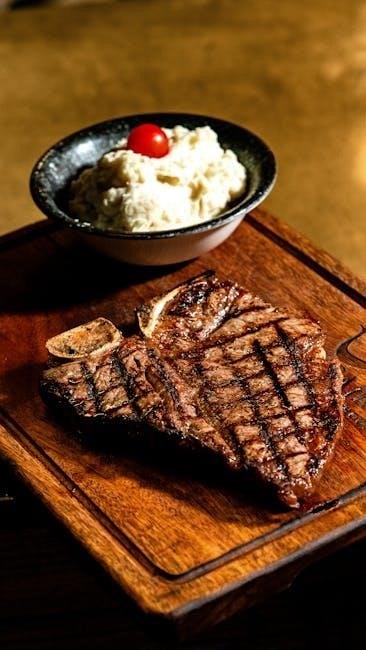
Remarkable Meats: The Core of Jack Stack
Jack Stack BBQ truly centers its reputation around its “Remarkable Meats,” a prominently featured section within the PDF menu. These meats are described as “Hickory Smoked,” emphasizing the traditional cooking method that imparts a distinctive and beloved flavor profile. The menu clearly positions these selections as the foundation of the dining experience.
The Freight House menu (2021-09-20) specifically details “Southern Jack” and “Poor Russ” as key meat options, both consistently priced at $14.50. This suggests a focus on offering quality, signature cuts at a standardized price point. The availability of “Chopped Burnt Ends” further solidifies the importance of expertly prepared meats.
The emphasis on these meats isn’t merely descriptive; it’s a core branding element, signaling Jack Stack’s commitment to barbecue excellence and a dedication to slow-smoked, flavorful proteins. These selections are the heart of the menu.
Southern Jack ⎻ Detailed Breakdown
According to the Freight House menu PDF (dated 2021-09-20), “Southern Jack” is listed under the “Remarkable Meats” section, priced at $14.50. While the menu doesn’t provide a detailed ingredient list or description of the cut itself, its placement suggests it’s a signature offering and a customer favorite. The simple listing implies a focus on the quality of the hickory smoking process rather than complex preparation.
The absence of further elaboration encourages diners to experience “Southern Jack” firsthand, relying on Jack Stack BBQ’s reputation for expertly smoked meats. It’s presented as a straightforward, classic barbecue option. The consistent pricing alongside “Poor Russ” indicates a similar portion size and perceived value.
Essentially, “Southern Jack” is positioned as a foundational element of the Jack Stack experience, relying on the inherent appeal of well-smoked meat.
Poor Russ ౼ Detailed Breakdown
The Freight House menu PDF (dated 2021-09-20) lists “Poor Russ” within the “Remarkable Meats” section, mirroring the price of “Southern Jack” at $14.50. Similar to its counterpart, the menu offers no specific details regarding the cut of meat or preparation method used for “Poor Russ”. This minimalist approach suggests Jack Stack BBQ prioritizes the smoking process and the inherent flavor of the meat itself.
The lack of a detailed description invites customers to discover the unique characteristics of “Poor Russ” through personal experience. Its equal pricing to “Southern Jack” implies a comparable portion size and overall value proposition. It’s presented as a core barbecue offering, emphasizing simplicity and quality.
“Poor Russ” stands as a testament to Jack Stack’s confidence in its smoking techniques, allowing the meat to speak for itself.
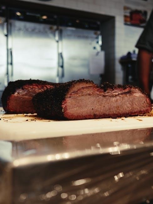
Chopped Burnt Ends ⎻ A Signature Item
Jack Stack BBQ’s reputation is significantly built upon its celebrated Chopped Burnt Ends, a menu highlight detailed in the Freight House PDF (2021-09-20). While the base price isn’t explicitly listed as a standalone item, it’s prominently featured within the “Combination Plates” section, offering a 1/3# choice alongside Beef Brisket, Pulled Pork, Turkey, and Sausage.
The menu also showcases a specialized variation: “Smokin’ Russ,” priced at $15, which elevates the Chopped Burnt Ends with the addition of jalapeños, spicy sauce, and cheddar cheese. This suggests the standard Chopped Burnt Ends are unadorned, allowing the rich, smoky flavor to take center stage.
The prominence of this item on the menu underscores its importance to Jack Stack’s identity and customer appeal, solidifying its status as a signature offering.
Combination Plates: The 1/3# Choice
Jack Stack BBQ’s PDF menu (dinner-freight-house-2021-09-20.pdf) features appealing “Combination Plates,” allowing diners to curate a personalized meal. These plates offer a generous 1/3# portion, with a choice of four distinct meats: Beef Brisket, Pulled Pork, Turkey, and Sausage. This format caters to varied preferences and enables sampling multiple flavors.
The menu doesn’t detail specific pricing for individual meat combinations within the plate; however, it’s clear this is a core offering designed for customization. The inclusion of fries with each plate adds value and completes the meal.
Notably, the “Smokin’ Russ” option, featuring Chopped Burnt Ends, jalapeños, spicy sauce, and cheddar, can also be considered a specialized combination, priced at $15, showcasing the versatility of these plates.
Beef Brisket Options
The Jack Stack BBQ menu, as detailed in the PDF (dinner-freight-house-2021-09-20.pdf), prominently features Beef Brisket as a key component of their “Combination Plates.” Customers selecting the 1/3# Combination Plate have the flexibility to include Beef Brisket alongside other meat choices like Pulled Pork, Turkey, or Sausage.
While the PDF doesn’t explicitly list a standalone price for Beef Brisket, its inclusion in the Combination Plate suggests it’s a popular and highly valued option. The menu focuses on the plate’s overall value, rather than itemized meat costs.
Furthermore, the “Smokin’ Russ” offering, a specialty Chopped Burnt Ends dish, utilizes Beef Brisket as its foundation, elevated with jalapeños, spicy sauce, and cheddar, demonstrating the versatility of this cut within Jack Stack’s offerings.
Pulled Pork Options
According to the Jack Stack BBQ dinner menu PDF (dinner-freight-house-2021-09-20.pdf), Pulled Pork is a cornerstone offering, particularly within the customizable 1/3# Combination Plates. Diners can build their ideal meal by pairing Pulled Pork with Beef Brisket, Turkey, or Sausage, creating a diverse flavor profile.
The menu doesn’t detail a separate price for Pulled Pork alone; instead, it’s presented as part of the Combination Plate value proposition. This suggests Jack Stack emphasizes the overall meal experience and the ability to sample multiple meats.
The “Southern Jack” and “Poor Russ” options, both priced at $14.50, showcase the restaurant’s remarkable meats, and Pulled Pork serves as a viable and popular choice for those seeking a classic BBQ flavor. It’s a fundamental element of their menu.
Turkey Options
The Jack Stack BBQ dinner menu PDF (dinner-freight-house-2021-09-20.pdf) clearly positions Turkey as a key component of their 1/3# Combination Plates, offering a lighter alternative to the richer beef and pork options. Like the other meats, it’s designed to be mixed and matched, allowing customers to personalize their BBQ experience.
The menu doesn’t list a standalone price for Turkey; its value is integrated within the Combination Plate structure. This encourages exploration of different meat combinations, showcasing Jack Stack’s commitment to variety.
Choosing Turkey alongside Beef Brisket, Pulled Pork, or Sausage provides a balanced meal. While not highlighted with a signature preparation like “Smokin’ Russ,” Turkey remains a consistently popular and readily available choice for those preferring a leaner protein within their BBQ feast.
Sausage Options
The Jack Stack BBQ dinner menu PDF (dinner-freight-house-2021-09-20.pdf) features Sausage as a versatile protein choice within the popular 1/3# Combination Plates. It’s presented as a standard offering, allowing diners to build a customized BBQ experience alongside Beef Brisket, Pulled Pork, and Turkey.
Like the other meats, the menu doesn’t detail specific sausage varieties, suggesting a consistent, house-made recipe. Its pricing is embedded within the Combination Plate cost, rather than being offered as a standalone item. This encourages customers to sample multiple meat options.
Sausage provides a different textural and flavor profile compared to the smoked meats, offering a savory complement. It’s a reliable choice for those seeking a classic BBQ accompaniment, consistently available and well-received by Jack Stack patrons.

Specific Menu Items & Descriptions
Jack Stack BBQ’s menu boasts signature items like Smokin’ Russ, a spicy burnt end creation with jalapeños and cheddar, detailed in the PDF.
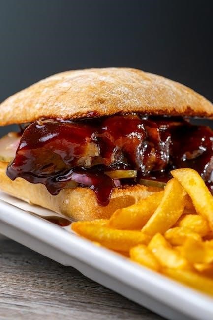
Smokin’ Russ ⎻ Spicy Burnt Ends
Smokin’ Russ is a standout offering at Jack Stack BBQ, prominently featured within the dinner menu PDF (freight-house-2021-09-20.pdf). This dish elevates the classic burnt ends experience with a fiery kick, appealing to those who enjoy a bolder flavor profile.
The PDF clearly indicates that Smokin’ Russ consists of chopped burnt ends generously combined with jalapeños, imparting a noticeable heat. This is further enhanced by a special spicy sauce and a topping of melted cheddar cheese, creating a harmonious blend of textures and tastes.
Priced at $15 as of September 20, 2021, Smokin’ Russ represents a slight premium over the standard burnt ends, reflecting the added ingredients and unique preparation. It’s a popular choice for diners seeking a memorable and flavorful meal, readily detailed within the accessible Jack Stack BBQ menu PDF.
Sides Included with Meals
The Jack Stack BBQ menu PDF (dinner-freight-house-2021-09-20.pdf) explicitly states that all main entrees are served with a complimentary side of fries. This inclusion adds significant value to the meal, providing a classic accompaniment to the hickory-smoked meats.
While the PDF doesn’t detail options for side substitutions or additions, the standard offering of fries is consistently presented alongside each remarkable meat selection – Southern Jack, Poor Russ, and the various combination plates. This simplicity streamlines the ordering process and ensures a consistent dining experience.
The fries themselves are a traditional cut, designed to complement the robust flavors of the BBQ. Reviewing the Jack Stack BBQ menu PDF confirms this standard inclusion, making it a key component of the overall meal value and a frequently enjoyed element by patrons.
Fries ⎻ Standard Side
As clearly indicated within the Jack Stack BBQ menu PDF (dinner-freight-house-2021-09-20.pdf), fries are the designated standard side accompanying all dinner entrees. This consistent offering is a cornerstone of the Jack Stack dining experience, providing a familiar and satisfying complement to their renowned meats.
The PDF doesn’t elaborate on specific fry preparation details – whether they are seasoned, the cut style, or available dipping sauces. However, their inclusion is unwavering across the menu, from the Southern Jack to the Poor Russ, and all combination plate selections.
This simplicity in side options allows Jack Stack to focus on the quality of their core BBQ offerings. The fries serve as a reliable and readily available accompaniment, enhancing the overall value proposition detailed within the Jack Stack BBQ menu PDF.
Menu Variations & Locations
Jack Stack BBQ operates multiple locations, and while the core menu remains consistent, slight variations may exist between each restaurant’s PDF menu offerings.
Freight House Menu Specifics
The Freight House location’s dinner menu PDF (dated September 20, 2021) showcases a focused selection of Jack Stack BBQ’s signature items. Remarkable meats, like the Southern Jack and Poor Russ, are prominently featured, both priced at $14.50 and served with fries.
A key highlight is the availability of Chopped Burnt Ends, a customer favorite, alongside customizable 1/3# Combination Plates. Diners can choose from Beef Brisket, Pulled Pork, Turkey, or Sausage to create their perfect plate.
The Smokin’ Russ, a spicy variation of the burnt ends with jalapeños, spicy sauce, and cheddar, is also available for $15. This PDF provides a clear and concise overview of the dining options specifically at the Freight House, allowing patrons to easily plan their meal and understand the current pricing structure.
Other Jack Stack Locations & Potential Menu Differences
While the Freight House menu PDF provides a detailed snapshot, Jack Stack BBQ operates multiple locations, and subtle menu variations may exist. It’s important to note that not all locations necessarily mirror the dinner menu PDF from September 20, 2021, exactly.
Differences could include seasonal specials, location-exclusive items, or slight price adjustments. Although core offerings like Southern Jack, Poor Russ, and Chopped Burnt Ends are generally consistent, promotional items or side dish options might differ.
To ensure you have the most accurate information for a specific Jack Stack location, it’s recommended to consult the official Jack Stack BBQ website and navigate to the menu section relevant to that particular branch. Checking individual location PDF menus, when available, is the best practice for up-to-date details.

Accessing the Jack Stack BBQ Menu PDF
Jack Stack BBQ makes its dinner menu PDF easily accessible online. A direct link is available, and updated menus can be found on their official website.
Direct Link to the Dinner Menu PDF (freight-house-2021-09-20.pdf)
For immediate access to the Jack Stack BBQ dinner menu, specifically the Freight House location’s version dated September 20, 2021, you can utilize the following direct link: dinner-freight-house-2021-09-20.pdf.
This PDF document provides a comprehensive overview of their remarkable meats, including Southern Jack and Poor Russ, along with pricing as of that date. You’ll find details on their signature Chopped Burnt Ends and various combination plate options featuring Beef Brisket, Pulled Pork, Turkey, and Sausage.
The menu also outlines included sides, such as fries, and highlights specialty items like Smokin’ Russ. While this link provides a snapshot of the menu from a specific time, it’s a valuable resource for understanding their core offerings and historical pricing. Remember to check the website for the most up-to-date information.
Finding Updated Menus on the Jack Stack Website
To ensure you have the most current Jack Stack BBQ menu information, visiting their official website is highly recommended. While direct PDF links, like the one for the Freight House menu (dinner-freight-house-2021-09-20.pdf), are useful, menus are subject to change.
Navigate to www.jackstackbbq.com and look for a “Menus” or “Locations” section. These areas typically host the latest menu versions for each of their locations. Regularly checking the website guarantees you’re aware of any price adjustments, new menu items, or seasonal specials.
Jack Stack frequently updates their offerings, so relying on the website is the best practice. You can easily browse or download the PDF menus directly from their site, ensuring you have accurate details regarding remarkable meats, combination plates, and available sides before your visit.
Pricing & Value
Jack Stack BBQ’s pricing, as of September 20, 2021, shows Southern Jack and Poor Russ at $14.50, while Smokin’ Russ is priced at $15.
Current Pricing for Key Items (as of 2021-09-20)
Based on the Jack Stack BBQ dinner menu PDF dated September 20, 2021, several key items have established price points. The remarkably flavorful Southern Jack, known for its hickory-smoked goodness, is listed at $14.50. Similarly, Poor Russ, another signature meat offering, also carries a price tag of $14.50.
For those craving a spicier experience, Smokin’ Russ, featuring jalapeños and a spicy sauce, is available for $15. The popular Chopped Burnt Ends are also priced at $15. It’s important to note that these prices are specifically as of the date mentioned and are subject to change.
Combination plates, offering a 1/3# choice of various meats, are structured around these individual meat prices. Customers can build their ideal plate with options like Beef Brisket, Pulled Pork, Turkey, or Sausage, each contributing to the overall cost. All entrees are served with fries.
Assessing the Value Proposition of Jack Stack BBQ
Jack Stack BBQ presents a compelling value proposition, particularly when considering the quality and quantity of food offered, as detailed in their menu PDF. While individual meat prices like the $14.50 for Southern Jack or Poor Russ might seem standard, the inclusion of fries with each entrée enhances the overall meal deal.
The availability of combination plates, allowing customers to sample multiple meats for a single price, further boosts the value. The generous 1/3# portion size for each meat selection ensures a satisfying and filling experience. Considering the hickory-smoked preparation and the signature flavors, such as the spicy kick of Smokin’ Russ, the pricing reflects a commitment to quality.
Ultimately, Jack Stack BBQ doesn’t just sell barbecue; it offers a complete dining experience, balancing flavor, portion size, and price to deliver substantial value to its customers.

Historical Menu Changes
Jack Stack BBQ’s menu, documented in past PDF versions like the 2021 Freight House menu, has likely evolved with ingredient costs and customer preferences over time.
Evolution of the Jack Stack Menu Over Time
Tracing the Jack Stack BBQ menu’s evolution requires examining archived PDF versions. Comparing the “dinner-freight-house-2021-09-20.pdf” to earlier iterations would reveal shifts in pricing, item availability, and potential additions or removals. For instance, the current menu prominently features “Remarkable Meats” like Southern Jack and Poor Russ, consistently priced at $14.50 as of September 20, 2021.
However, older menus might showcase different specials or seasonal offerings. Observing changes in side dish options, or the presentation of combination plates, would illustrate the restaurant’s responsiveness to customer feedback and market trends. The introduction of items like “Smokin’ Russ” – a spicy burnt ends variation – demonstrates innovation. Analyzing these PDF snapshots provides valuable insight into Jack Stack’s culinary journey and adaptation over the years, reflecting a commitment to quality and customer satisfaction.